
In this article, we show you how to build a current voltage measurement system. It measures AC current and AC voltage with the ACS712 current sensor and the ZMPT101B voltage sensor. Besides working as a wattmeter, this circuit also acts as a voltmeter and an ammeter, which measure voltage and current respectively. If you wire the connections correctly, the ACS712 measures current accurately. We have worked with other current detectors, like SCT-013-030 and INA219, but they are not as precise. For more on the board, visit the Raspberry Pi website.
The ACS712 is a low-cost, smaller AC sensor, so we chose it for this project instead of a conventional current transformer. It measures current accurately when current flows. It detects the magnetic field around an AC wire and gives an analog output voltage. Then the microcontroller processes that output to measure the current flow through the load.
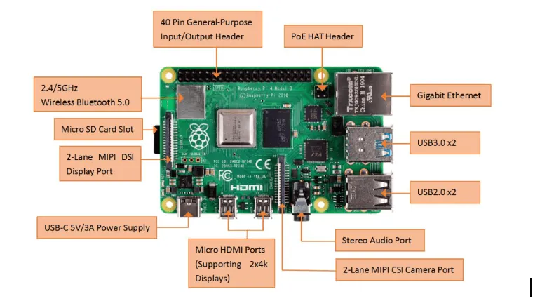
Raspberry Pi for the Current Voltage Measurement System
Raspberry Pi is a small single-board computer. When you connect a keyboard, mouse, and display, the Raspberry Pi acts as a mini personal computer.
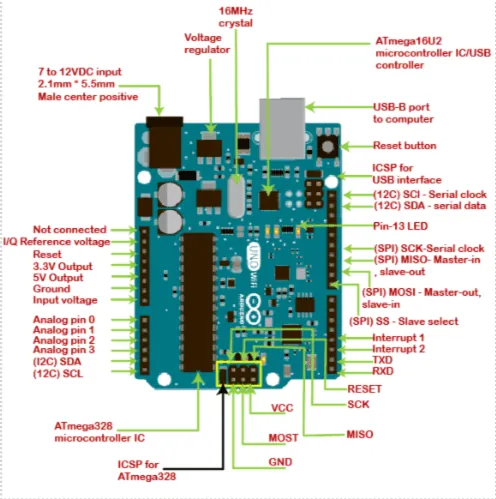
Arduino Uno – Arduino Uno is a microcontroller board based on the ATmega328P. The board includes an ICSP header, a USB connection, a power jack, a 16 MHz ceramic resonator, a reset button, and 14 digital input/output pins (6 of which can be PWM outputs).
Hardware Specifications for the Current Voltage Measurement System
These are some common hardware components:-
- Raspberry Pi
- Arduino Uno
- Bread Board
- ZMPT101B Voltage sensor
- ACS712 Current sensor
- Jumper wire
- Switch Board
Software Specifications for the Current Voltage Measurement System
These are some common hardware components:-
- Arduino Compiler
- MC Programming Language: C
- VNC Viewer for Raspberry Pi
- MC Programming Language of Raspberry Pi: Python
- IP Scanner (for finding the IP Address of Raspberry pi)
Connection of Device and Software Setup – Step By Step
These are some common hardware components:-
- Hardware connection of voltage sensor with Arduino Uno as well as with current sensor.
- Hardware setup for serial communication.
- Raspberry Pi Software setup.
- Serial communication (with UART).
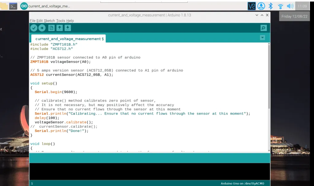
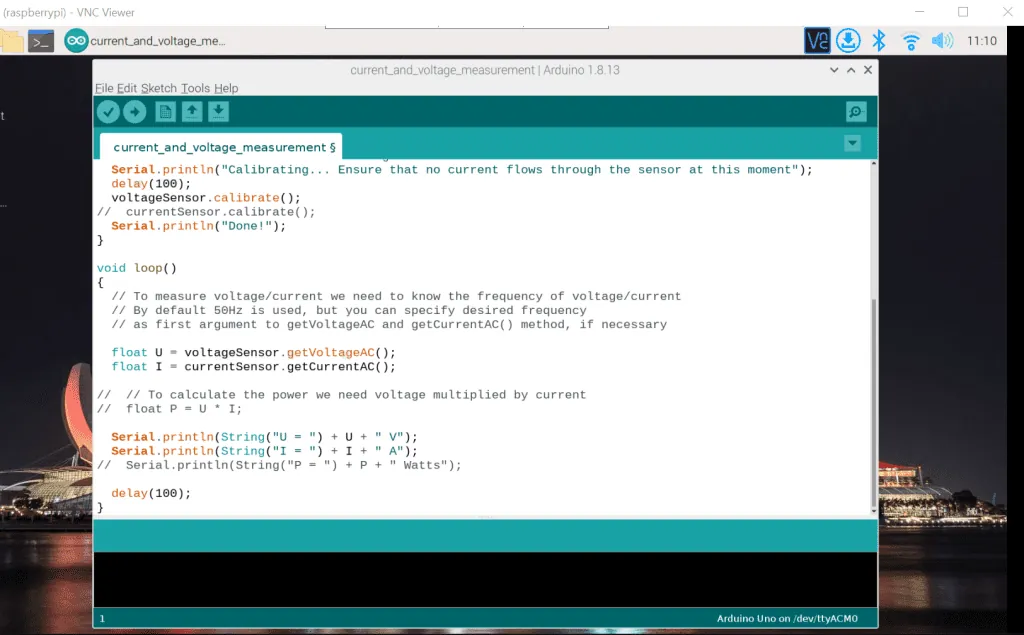
- Code for current and voltage measurement in Arduino IDE.
1. Hardware connection of voltage sensor with Arduino Uno and current sensor respectively
First, connect the microcontroller (the Arduino Uno) and the sensors. Set the 5v and GND (ground pin) of the Arduino Uno to the breadboard. One point of the breadboard is common for the GND (ground pin). The other 5v pin is common for the power pin.
After that, we use a current sensor and a voltage sensor to measure the current and the voltage, respectively. At the beginning of the connection, check whether our voltage sensor model is ZMPT101B or not. Similarly, check if the current sensor model is ACS712.
- Connection of Voltage sensor and Arduino Uno
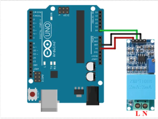
Begin by checking the 5v pin, OUT pin, and GND pin of both devices. Then connect the pins. The GND pin of the voltage sensor has to be connected to the GND pin of the Arduino Uno device. The 5v pin of the Arduino Uno has to be connected to the VCC pin of the voltage sensor. Also, make sure the OUT pin of the voltage sensor is connected to the input pin of our Arduino Uno device, i.e., A0.
Connection of current sensor and Arduino Uno
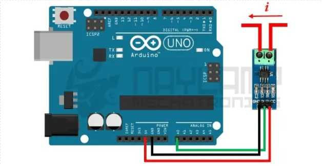
You can now check the 5v pin, GND pin and input pin of both devices. Connect according to the same pin of our Arduino device and sensor. Then, connect the 5v pin of the device to a current sensor of the VCC pin, the GND pin of the device connects to the sensor of the GND pin, and then the input pin of the device, i.e., (A1) is connected to the current sensor of OUT pin.
2. Hardware setup for serial communication
We connect the Raspberry Pi and Arduino for serial communication via USB. A USB cable connector is the easiest way to connect an Arduino Uno and Raspberry Pi.
Note: Make sure your Arduino Uno is connected to a computer so that you can upload the code. Then, you will need to connect the USB cable to the Raspberry Pi. Through this cable, the Raspberry Pi can power the Arduino.
3. Raspberry pi software setup
Download and install the Arduino IDE in Raspberry Pi OS.
Install Python Serial library on Raspberry pi
We install the pyserial library with the command below, which gives us the serial connection interface:
// sudo pip install pyserial
Locate the Arduino board
Typically, you see the Arduino appear as /dev/ttyACM0 or /dev/ttyUSB0 (sometimes the number is different
For example: /dev/ttyACM1) when connected via USB cable.
4. Serial communication (with UART)
For the serial communication of the Raspberry pi and Arduino Uno UART protocol is used.
UART protocol
UART stands for ‘Universal Asynchronous Reception and Transmission’. Asynchronous allows communication between the two boards. Arduino has one UART in our device that can be seen either with a USB cable or from the RX/TX pins. Neither pin used at the same time. On the Raspberry Pi, it can connect to many serial devices on the USB ports. Using Raspberry Pi also uses the GPIOs (RX0/TX0) for an additional UART.
5. Code for current and voltage measurement in Arduino IDE
Let’s start with a simple program.
- Go to the Arduino IDE in our Raspberry pi VNC viewer
- Create a new file and save it on the Arduino IDE
- After saving the code, compile the code mentioned above
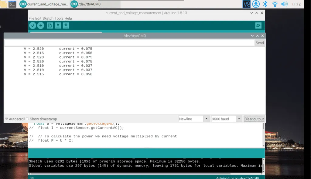
- Go to the tools setting. Choose serial monitor
- Inside the serial monitor, you will see the current and voltage reading
Code for current and voltage measurement
Testing the Application
To test the current voltage measurement system, connect the Raspberry Pi and the Arduino Uno and check the power supply. Before connecting the current sensor, ensure to check the ground pin (GND), voltage output pin (VCC), and input pins of our sensor. Then solder all of the pins with a soldering iron. Check the input pins, voltage pin VCC, and GND pins for the voltage sensor. After you connect the device to the 3-phase line, connect the relay to protect the device from damage.
For connection of the relay and Raspberry Pi, connect the JD-VCC pin of the relay to voltage pin 3.3 v of the Raspberry Pi and the VCC pin of the relay connects to the 5v of our Raspberry Ri. Similarly, the relay’s input pin (IN1) is connected to the GPIO12 pin and its ground pin (GND) is connected to the GND pin. Now we can connect our relay module to the supply. A blinking red light shows the relay is ON. When it is not blinking, the relay is OFF.
Advantages
- We can easily measure current and voltage using the Raspberry Pi and Arduino Uno.
- We can easily move both microcontrollers from one place to another.
- Its quite cost-effective.
- We can measure both current alternating current as well as direct current
- It is an easy-to-use tool.
Disadvantages
- Raspberry Pi cannot be operated on Windows operating system.
- If we use it continuously for 6-7 hours. then it heats above 70-degree Celsius.
- It lacks graphics processor
- It lacks internal storage in our microcontroller, which is why its performance is lesser than others.
- Its boot time speed is very slow during the initial setup.
- Sometimes, the system takes time to upload the data depending on the internet speed and module baud rate.
Conclusion
The current voltage measurement system we presented measures current and voltage through a Raspberry Pi and Arduino Uno serial connection. The multiple use cases of this using our Arduino IDE monitor include energy management, saving power from the power section, automatic control of energy meter, to make customers monitor their energy usage pattern, and power flow graph.
For more detail about the ACS712 current sensor follow the below reference link:-
https://embedded-lab.com/blog/a-brief-overview-of-allegro-acs712-current-sensor-part-1/
Need a website or web app?
We build on WordPress, Webflow, Shopify, Bubble and custom stacks.